
With an eye towards next winter I started thinking about a little chap to fly. The rtf models around didn’t grab me and I have collected enough transmitters already.
45 years ago in my youth we spent many hours at the table building balsa kits and had a few plans for free flight planes powered with Cox 049 glow engines. My thoughts turned to an old timer balsa plane. A search of outerzone plans;
Outerzone : Free plans : Listing of free vintage model aircraft plans to download
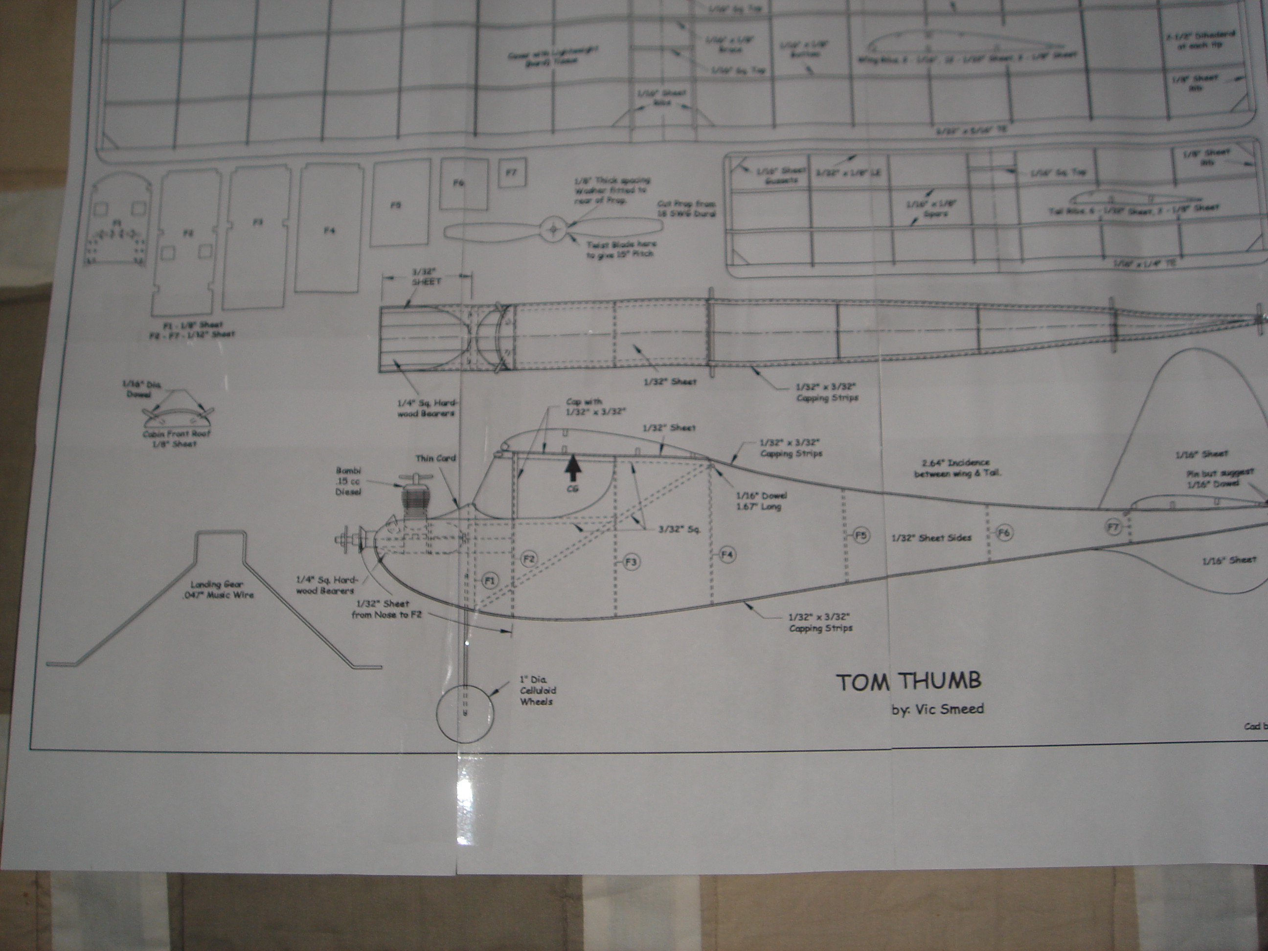
turned up a few candidates but the one that caught my eye and one I remember well was the Tomboy designed by Vic Smeed. He also designed a smaller version of this which he named Tom Thumb. The plans originally published in 1954 were for a free flight plane powered with a Bambi 0.15cc diesel with the prop reversed because it was a bit over powered.
Plans in pdf format were available from outerzone so I downloaded them. Printed and pasted together you get;
Since I wanted to use this indoors I needed to find a suitable electric motor and modify the plane for 3 channel rc. A visit to Phoenixmp and a long chat with Stan Yeo resulted in him giving me useful advice on the mods needed to the fuselage formers to modify the fuselage to accommodate the rx and servos. He had some neat little 2g micro servos. So armed with 6 sheets of 1/32″ balsa and the servos I set about the plans. A tip Stan gave me was make up the formers by gluing the 2 sheets of balsa with the grain running 90 degrees to each other. A form of ply made with balsa. Instead of solid formers he advised using these laminated sheets and then designing and cutting them as frames.
Next part was to make blanks of all the parts that I needed so that I can build more or repair this model fairly easily. I took the bits and glued them to ply and cut them out with a saw;
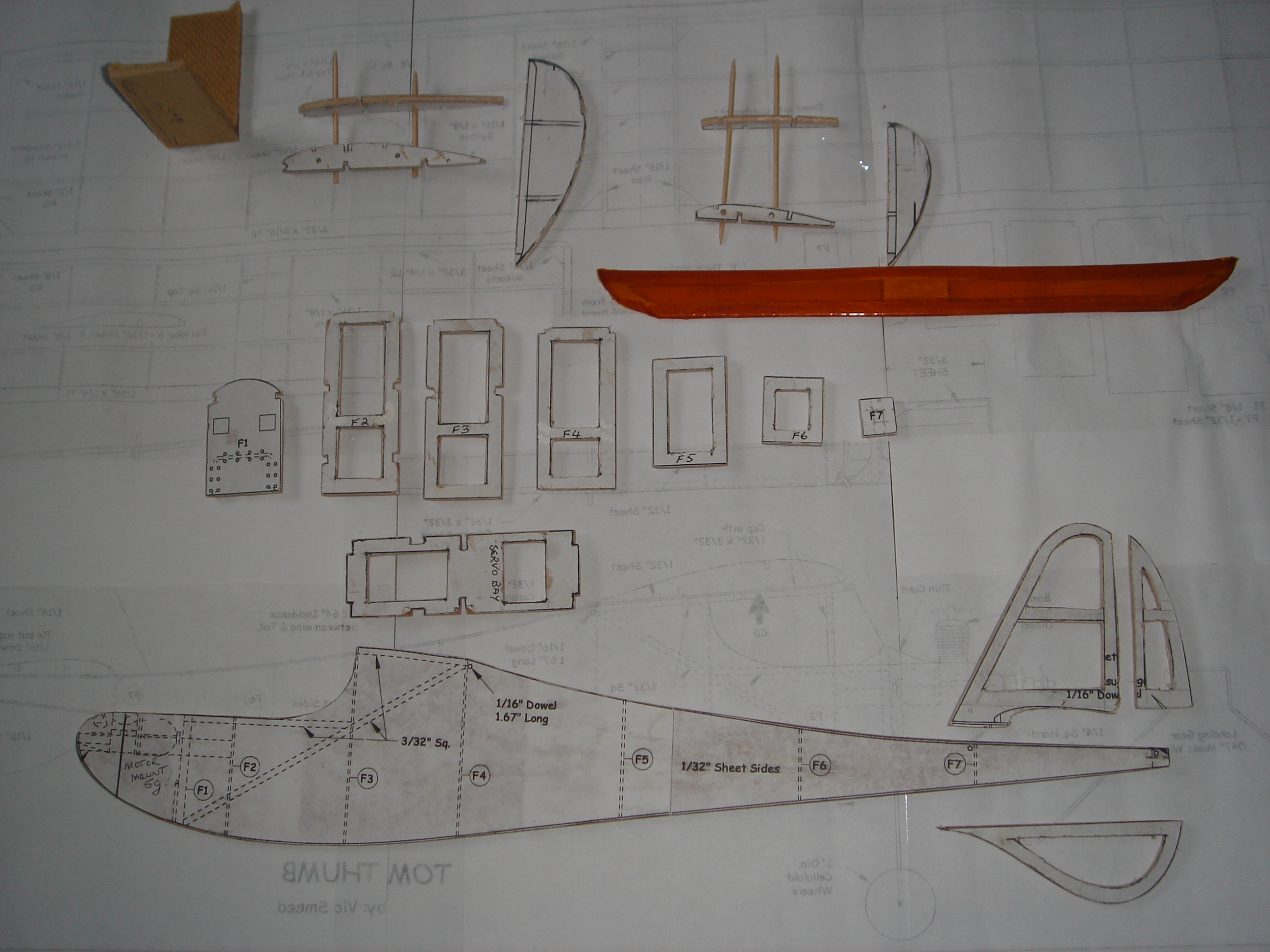
I wanted to add some nice wing tips so designed these and cut them as well as a tray for the servos and rx. So above from left to right and top to bottom is a little stand to get the correct wing dihedral, wing ribs, wing tip, stab ribs, stab tips, elevator, fuselage formers with central division to take the tray and divide the central section in half, servo tray that mates with formers f2, f3 and f4, the fuselage, vertical stab, rudder and the tail skid.
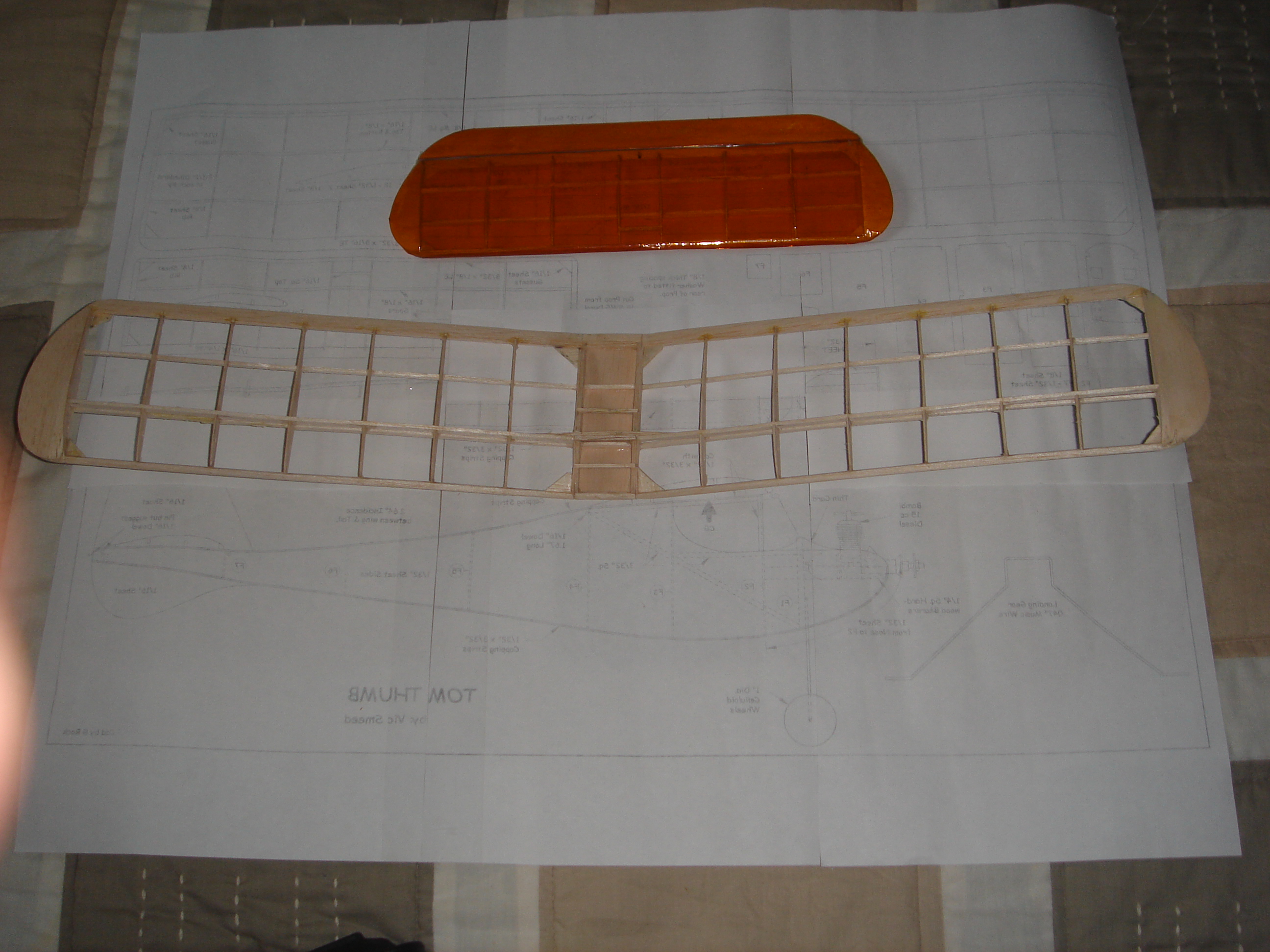
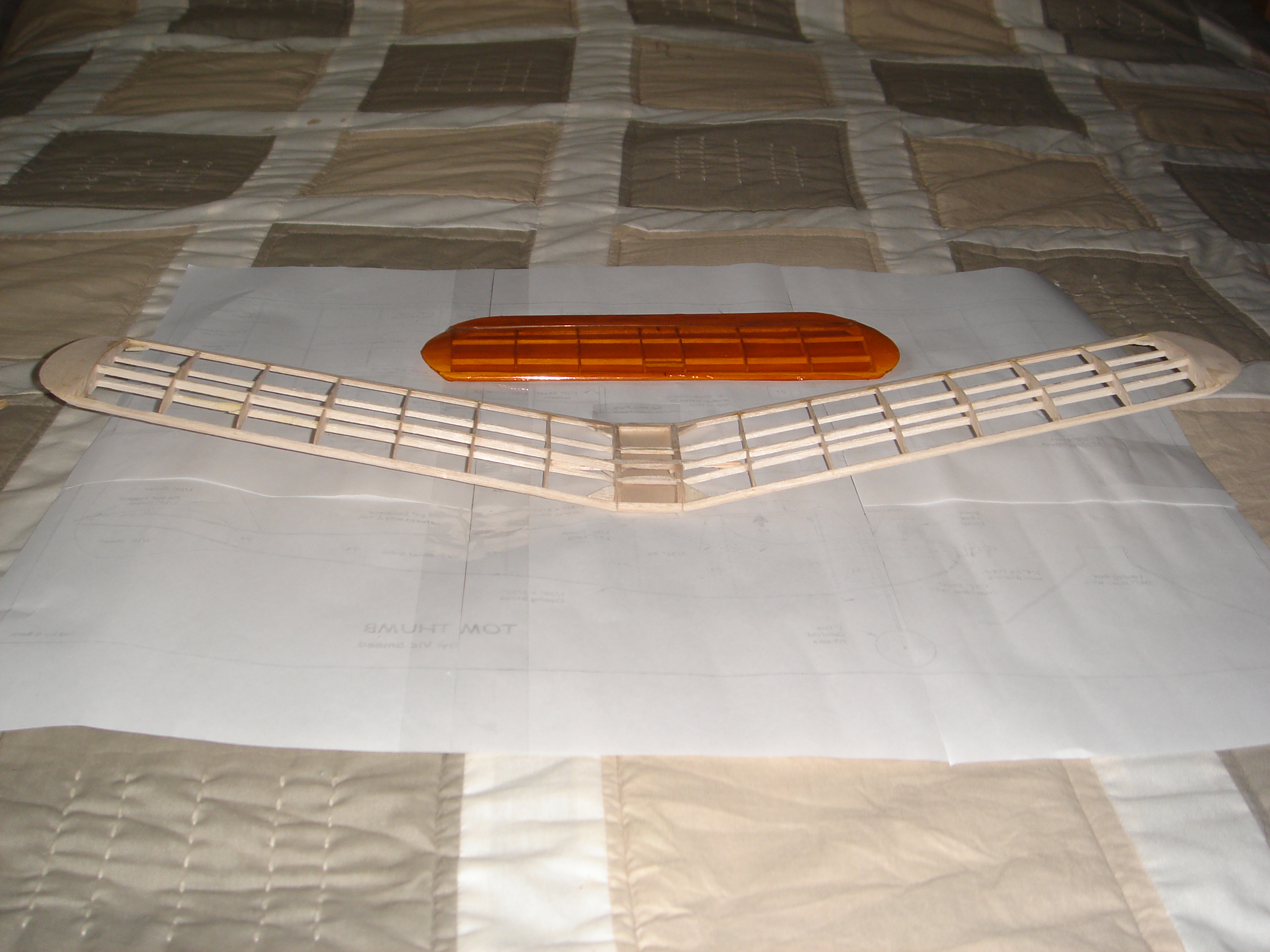
Built the stab and wings first. Cut oblong sections bigger than the ribs and then using tooth picks through them sandwiched them between the ply ribs. They were all shaped and cut using this system. This worked well and resulted in very standard ribs. The horizontal stab went together very easily. I used a 50mm thick piece of polystyrene as a build board for everything. I them built the wings using the same system. All the spars were made by cutting strips of 1/32″ balsa and gluing them together to the relevant thickness. A real challenge for the brain involving fractions  . Since I have also been raised in metric and my vernier caliper is also metric this meant conversions. The wing was built as a single unit and then cut at the centre and using the little stand the correct dihedral for each side was achieved. Below is the wing and horizontal stab which I have covered with Solarfilm.
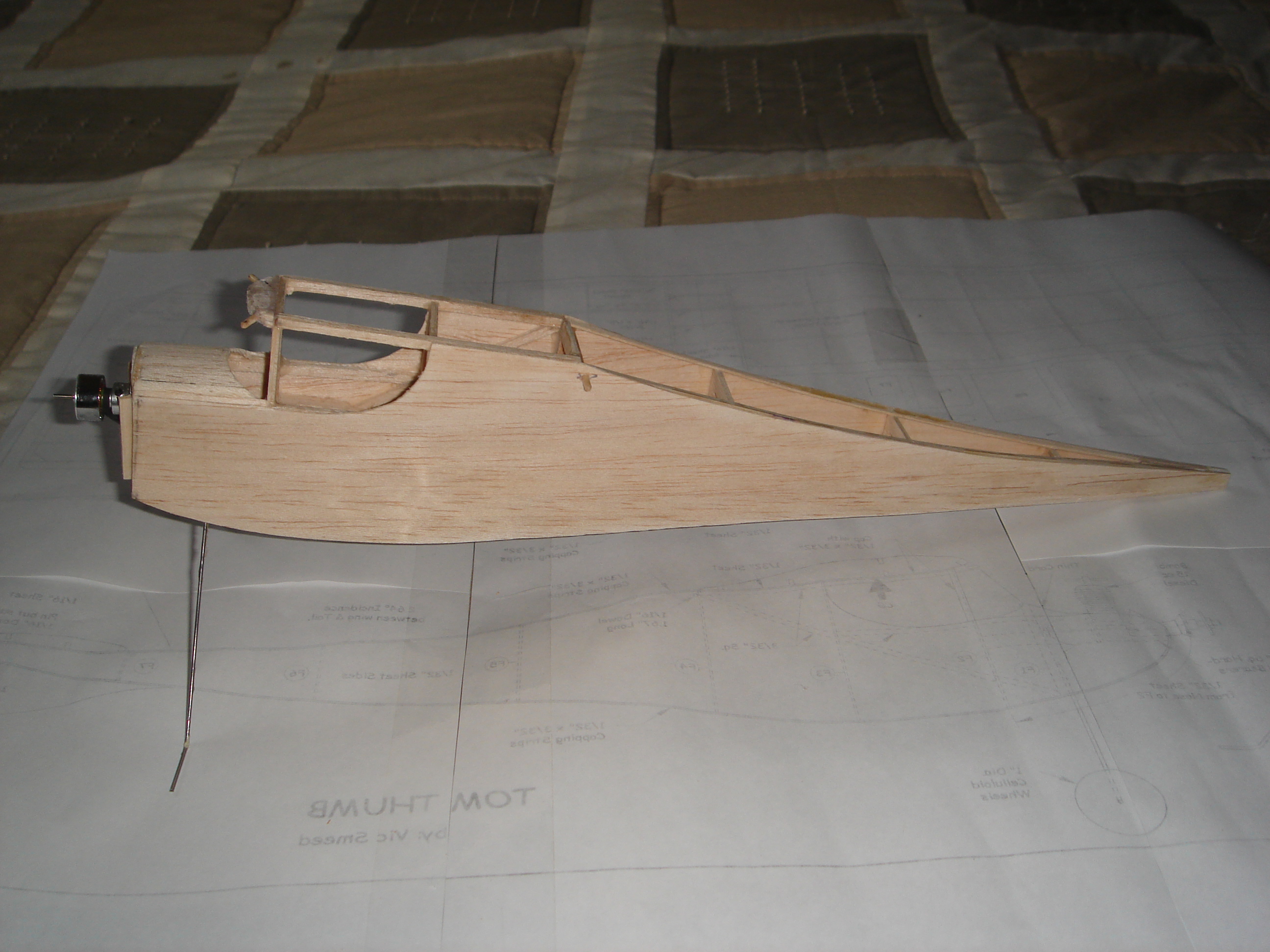
Next was the fuselage. This went together fairly easily as the formers were very accurate. Because the parts are so small it was very fiddly.
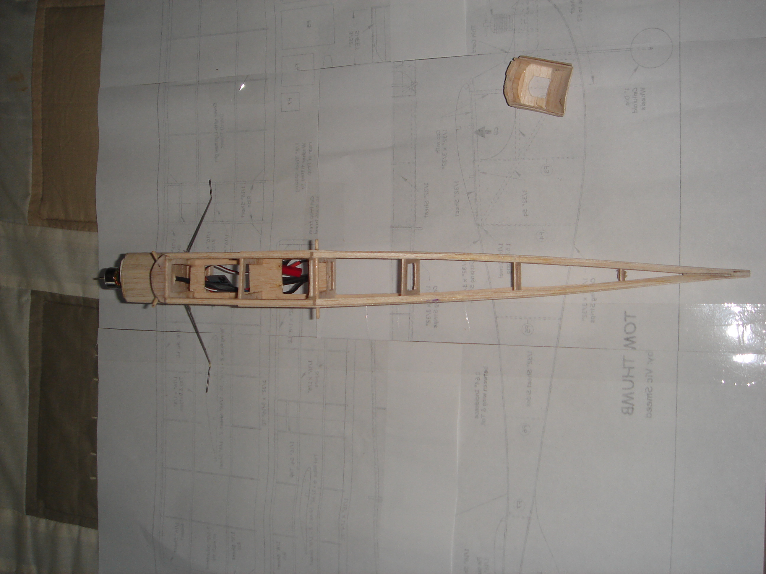
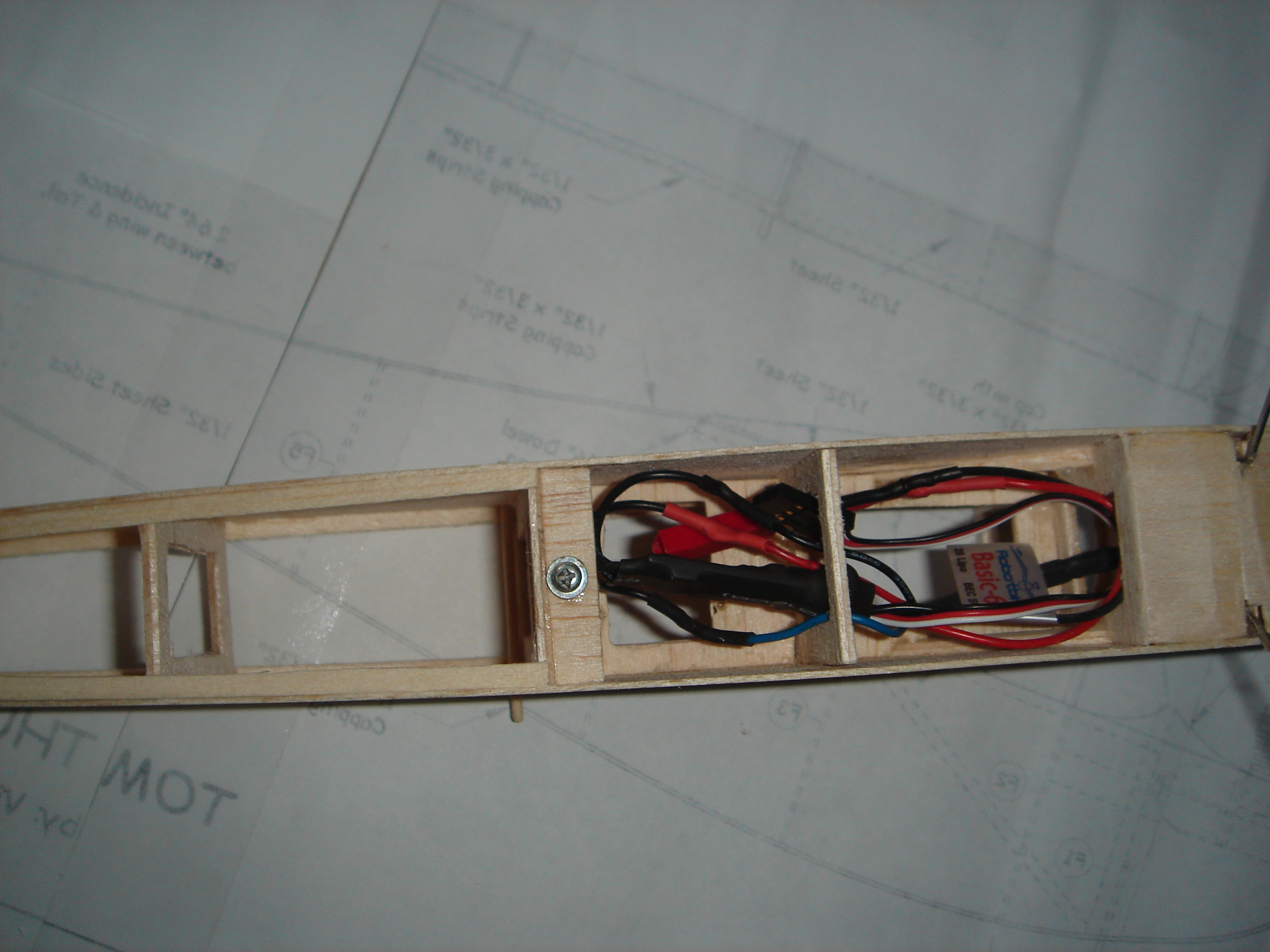
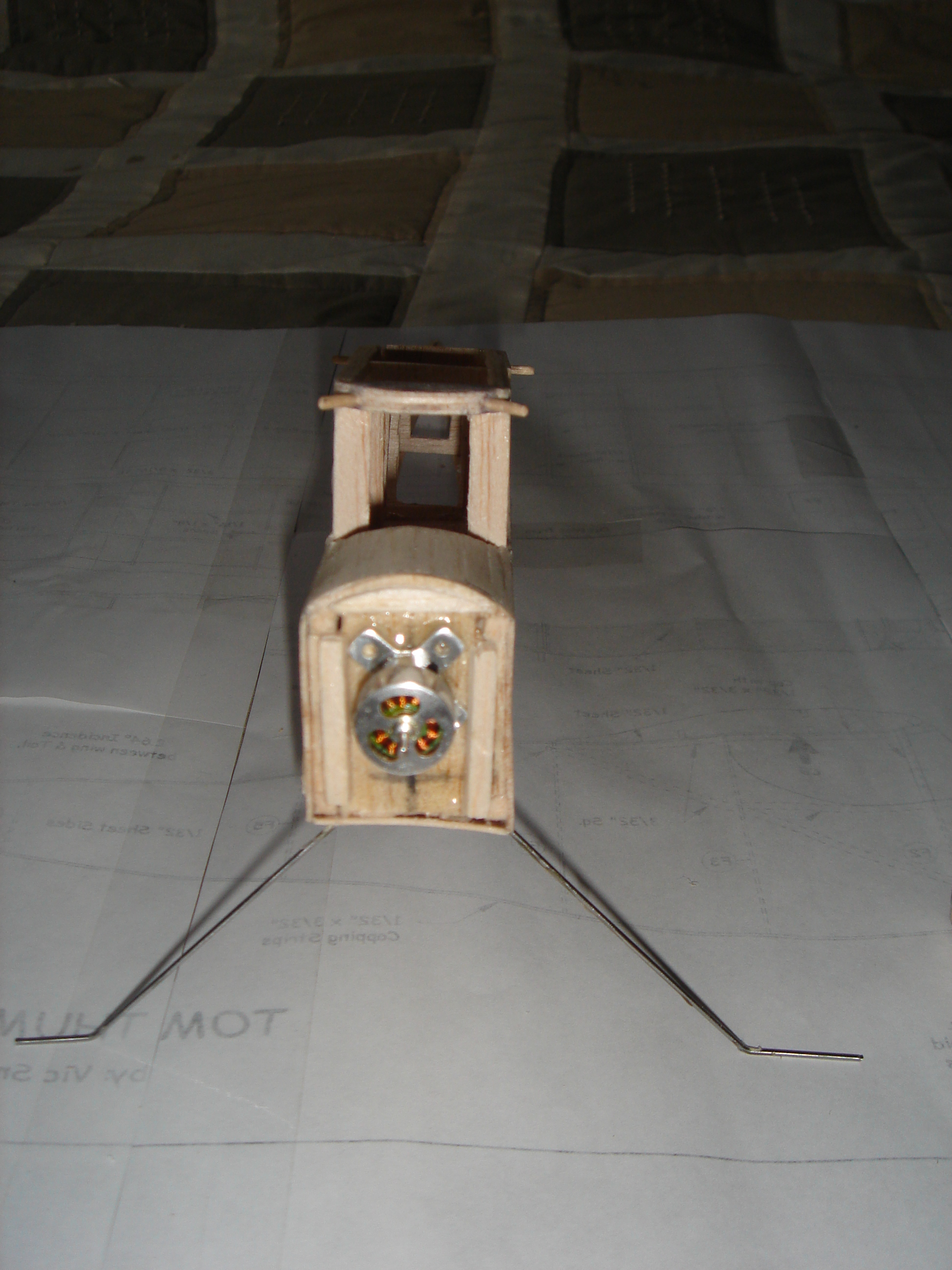
I managed to locate a little 5g motor, along with a 6g 6A ESC. The motor uses a 2S lipo and managed to find 320 maH 2S lipo weighing 16g. Since the original engine was 37g I am well in the range. The motor produces 80g of thrust and the target weight is 60g. I am using an Orange 6ch rx which without the case is 3g. The current weight is 57g. With covering it will probably end up at around 70g. With the battery around 86g. Because the thrust is a shade under the gross weight the plane will be very over-powered so should give some reasonable flight times.
The motor mount requires a 2mm screw and since I didn’t have any and cannot locate any locally I decided to epoxy it to the firewall. This is not a big issue as the mount can be separated from the motor so if I need to I can easily just replace the motor. I used the original thrust line as per plan. Have sheeted over the engine bay area where the glow engine cylinder would have gone and then separated it. Once covered it will then just slip over the motor and be secured with a bit of tape;
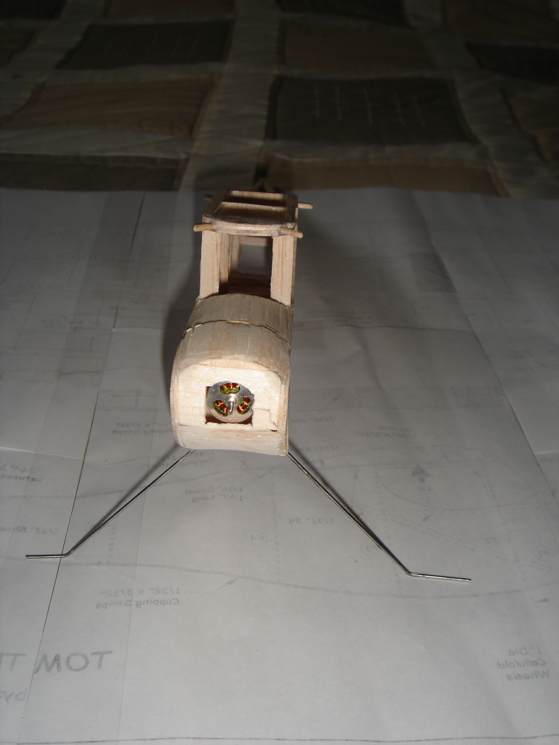
The electrics are wired up and tested. Need to install the servos and make the control rods. This is going to be very fiddly because there is no space to work in and I have already had to use a pair or artery forceps to hold things because my fingers are too big and too short to reach in there. Finally all the covering needs to be done. The Solarfilm is great stuff and I have been impressed with the finish.
Finally wait for a very calm day and see if it flies. Will keep you updated.
Rob